Mechanical Engineering
Home > Electronics Development > R&D processes > Mechanical Engineering
Mechanical Engineering
The goal of mechanical engineering is to enclose and protect the electronics from environmental influences.
These include contamination such as dust, liquids such as salt water, chemicals like fuel, cleaning agents and various temperature influences as well as vibration.
Interfaces to the electronics, such as the thermal connection to the cooling plate, the connector contacts and the vibration damping of SMD components on the printed circuit board, must be developed and designed. Furthermore, the interface to the environmental side must be adapted mechanically and thermally, i.e. assembly via screw, clamp or plug connection as well as electrically through the connector system. After the right housing has been developed for a product, it is ready to work for the whole life time of the product, being protected from any kind of environmental influence.
DESIGN
Both 2D and 3D design software is used to create and develop the concept from mechanical architecture to the final product.
The individual parts and assemblies and their derived drawings are created with these design tools. In addition, virtual collision checks can be carried out.
Used 3d consturction software:
Creo Parametric 7.0
(with Cetol add-on for statistical tolerance design)
Used 2D construction software:
Draftsight Professional
DEVELOPMENT
In order to check the developed design for its robustness, usability and manufacturability, various simulations are carried out on individual components and assemblies. The scope and content of the simulations vary depending on the component and requirement or desired analysis:
seal design, profile shape of the sealing lips: size, number of sealing lips, Shore hardness, compression set = disturbance pressure vs. contact pressure over the service life
- Modal analysis of A-parts: PCBA, housing, cover, ECU/actuator, fixtures for validation
- Thermal expansion during installation, i.e. at the ECU level – thermal expansion and stress analysis of individual components in the integrated state. Behavior of the components under the influence of temperature
- Encapsulation/Filler simulation
- Sealing design; profile of the seals: size, number of seals, Shore hardness, compression rest = wind load vs. contact load over lifetime
- Modal analysis of A components: PCBA, casing, cover, ECU/actuator, clamping systems for validation
- Heat expansion when installed, i.e. at the ECU level – heat expansion and tension analysis of individual components as installed. Behavior of the components under the influence of temperature
- Encapsulation/filler simulation
Used simulation software: ANSYS, MOLD-FLOW
TEST
Various methods and devices are used to check whether the manufactured component meets the necessary requirements. The analysis steps and depth may vary depending on the product. This includes:
- Geometric tests and evaluations via 3D scan
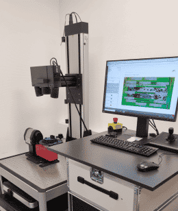
Material analysis by microscope: 20-2000x magnification; 3D scan function for measurements
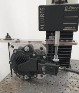
- Force measurement machine, e.g. plug-in tests, programmable force measurements 10N-1kN
Roughness measurements usually of surfaces or sealing surfaces
Shore hardness measurements e.g. of encapsulation applications
- Laser marking capability test
- Geometrical testing and evaluation via 3D scan
- Materials analysis via microscope: 20-2000x magnification; 3D scan function for measurements
- Force measurement machine e.g. connection tests programmable force measurement 10N-1kN
- Roughness measurements, generally of exposed or sealing surfaces
- Shore hardness measurement e.g. of encapsulation applications
- Laser oscillation tests
Used hardware/software:
ATOS Q 3D Scanner, GOM Evaluation Software, Keyence VHX 5000, Alluris force measurement machine


ADDITIONAL EQUIPMENT:
With the aid of various additional machines, situations within the project that often require a lot of time can be accelerated.
With the FDM-3D printer, programming adapters can be realized for tests in early project phases in a very short time. Furthermore, during the concept phase the products can be quickly manufactured and presented to our customers. This gives an initial impression of the size of the product and its application very early on.
Used hardware/software: Stratasys FDM 3D printer
Validation
With validation, we ensure that the development fulfills all normative and specific customer requirements.
Our service offering is divided into 3 sub-areas: environmental validation, electrical validation and EMC validation.
We will be happy to personally advise you.
Would you like to learn more about our service portfolio or do you have a specific request? Our experts will be happy to help you.


