Manufacturing Technology
Home > Manufacturing Technology
EMS Manufacturing – Overview of Technologies
Because our EMS standards are global, our customers receive the same constant high quality from all Melecs sites. Thanks to these manufacturing standards, products can easily be made available on other continents, in accordance with the principle of “local for local”.
We coordinate our global standards through our own platform, the Melecs Production System. In this system, process, machine and software standards such as ERP and MES systems are standardized across all Melecs sites.
Through regular coordination at the platform level, we ensure the existence of a vital exchange of experience and coordinated further development. Our system architecture enables central evaluation and comparison of process key figures between the manufacturing sites and contributes to increasing quality and performance. Our customers benefit from more efficient processes and technologies at the highest level as well as from low costs when entering new markets.
Traceability
SMT
THT
Soldering processes
Depaneling
Inspection & Analysis
Module, System & Product Manufacturing
Testing
Gluing and Encapsulating
Protective Coating
Traceability
Melecs seamlessly fulfills the requirement for component and process traceability. Components, assemblies and systems are managed with serial numbers and production is digitally documented. The structured data is available for any analyses.

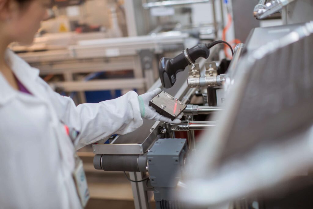
Incoming goods scanner
For a complete and detailed recognition of codes and labels. Components can thus be tracked throughout the entire production process. In this way, it can be tracked exactly which product, which batch / lot number / date codes of components have been installed when and where.
Line Lock (LILO)
LiLo is a solution developed by Melecs for monitoring and controlling SMT production lines. LiLo checks the machine settings by comparing the current programs and the tools used, such as solder paste and stencil, with the programs specified in the Melecs databases. If a deviation is detected, the PCBs are stopped before they can enter the corresponding machine.
Laser Identification
The laser marking system is used for the direct marking of printed circuit boards using CO2 lasers. The laser unit is mounted on a linear driven X/Y axis system above the transport system. The printed circuit board to be marked is taken over by a transport system, fixed and moved to the target level. The laser device then moves to the program-controlled positions and marks the predefined contents such as barcodes, data matrix codes, texts or logos on the product. The code contents are then verified and stored using a high-resolution camera. An optional software upgrade for detecting fiducials is used for position correction.
Handscanner
Surface-mount technology refers to a process in which the electrical components are attached directly onto the surface of a circuit board.
Pin-in-Paste is an assembly technology for wired components. These components are attached on the SMT line and soldered using a standard reflow process.
In stencil printing, solder paste is applied to the circuit boards. Electrical connections are formed. Then the components are mounted. The materials and equipment used are a stencil, a solder paste and a printer.
Dispenser technology is used in the manufacturing of electronic components for assembly and connection in order to hold components in place during soldering.
Complex or customer-specific components are placed using automatic mounting systems.
In assembly and connection technology for microelectronics, Package-on-Package is a manufacturing technique in which several chip casings are mounted over each other
THT (Through-Hole Technology)
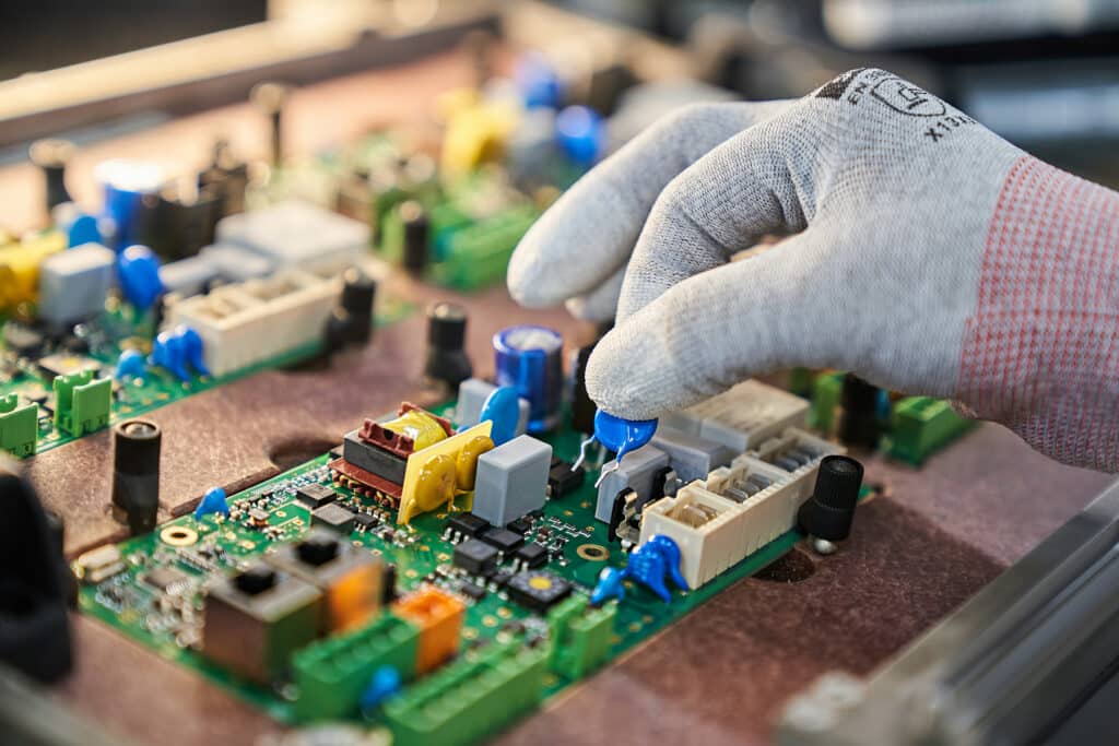
Through-hole technology, or THT, refers to a mounting technique for wired electronic components. In contrast to surface mounting (SMT), the components have wire connections and are larger. During assembly, these are inserted through contact holes in the circuit board and then connected to the track.
Press-in technology refers to a special solder-free connection technique for circuit boards. In this process, a pin is pressed into a through-hole. The pressing-in forms a gas-tight electrical connection that is reliable and durable. Press-in contacts are widely used today in the automotive industry .
Full automatic assembly of axial components (diodes, resistances, wire bridges).
Automated placing of special shapes (plugs, relays, block capacitors).
Automated placing of pins (multispring, action pin, compliant pin).
Automated placement of radial components (capacitors, varistors, LEDs).
For the population of circuit boards in small numbers, manual placement is both faster and cheaper. Through-hole technology (THT) in particular is very well-suited to the manual population of small series.
It is also a good choice for prototype manufacture and placing unusual components
Wave soldering
In wave technology, a flux is applied to the solder side, which is heated and guided by a single or double soldering wave. Unlike selective soldering, wave soldering involves soldering the entire PCB and not just a selected area.
Selective soldering
The components to be selectively soldered are usually surrounded by parts that have previously been soldered in a surface reflow process. The selective soldering process must be precise to prevent damage.
Ironing soldering technology
Hartmann® Iron Soldering - With this machine we build a product from 3 printed circuit boards connected with a flat cable. In its first production run, the machine solders the cable to the "wing" PCB, after inserting the PCB into the second device on the turntable, the "wing" PCB is soldered to the "main" PCB. The position of the cables must be adjusted manually before soldering. The operator is supported in this process by a camera system. As a first step, a suitable flux is applied to the circuit board. This is followed by the soldering process. After completion of the soldering process, the turntable is manually moved out of the machine. Important parameters such as the soldering temperature are controlled during the soldering process.
Reflow Soldering
Reflow soldering is the most common method for soft soldering of SMD components.
In this process, the assembly passes through a specific temperature curve. As a result, the applied solder paste melts and creates a connection between the component and the circuit board.
As a rule, this soldering process takes place in an inert atmosphere.
Vacuum Reflow Soldering
The additional use of the vacuum process in reflow soldering significantly increases the quality. Defects within a solder connection can be reduced to a few percent.
Milling
In modern production lines, the panels are separated by milling. Short connections are frequently cut with mills while longer connections are separated using cutting discs.
Circuit board panels are separated using a flexible mill that offers high quality requirements and high flexibility with high cut precision.
In contrast to common cutting processes, such as with an angle grinder, milling does not generate much tension.
V-Cut Technology
Depaneling with bifacial blade:
Panel (usually with pre-carved groove to guide, orient and reduce cut depth) is separated using two bifacial blades (a moveable one above, a fixed one below the panel).
Cutting with V-cutter rolling blade
Separation at pre-carved groove (for guiding, orienting and reducing cut depth) using one or two rolling blades.
With automated optical inspection, errors in production can be identified using image processing.
SPI stands for “solder paste inspection”. The aim of SPI is to detect errors by analyzing the state of solder paste deposits applied by a screen printer. The inspection results serve to optimize the printing process. The parameters of the screen printer are adjusted accordingly.
Automated X-ray inspection is used to inspect populated circuit boards. It is classified under automated optical inspection (AOI). But instead of light, X-rays are used to inspect the internal structure of electronic components such as contacts, connecting wires and soldering points.
A digital microscope uses a digital camera to display images on a computer monitor. The microscopes include a variety of observation methods and measurement functions.
This is a measurement method that uses light to determine physical parameters or directly properties of light.Tactile measuring systemTactile measuring delivers very accurate geometry measurements.
Tactile measuring delivers very accurate geometry measurements. It allows making precise tolerance measurements in the micrometer range and extensive recording of parts surfaces.
Module, System & Product Manufacturing
The quality-relevant assembly and inspection processes are fully automated. Collaborative robots, or cobots for short, are industrial robots that work together with people and that are not separated from these by safety barriers during the production process.

Manual Assembly
Manual assembly systems can be integrated in un-linked or loosely linked work stations in in-line or parallel setups (one piece flow). Assembly is done using manual tools. Linking may be through a drive-less slide, rollers or smooth surfaces. The assembly piece is passed on manually or via an inclined surface leading to the next work station.
Fully Automated Placing
The assembly piece is passed on manually or via an inclined surface leading to the next work station. The assemblies are generally moved manually, but this can also be automated. The assembly and testing processes and removal of the assembly pieces from the stations is automated.
You are currently viewing a placeholder content from Youtube. To access the actual content, click the button below. Please note that doing so will share data with third-party providers.
More InformationHalf Automated Assembly
In semi-automated systems, some of the assembly activities are carried out manually before or within the system. After the manual process, the assemblies are transported within the system using automatic transfer units (linear axes or robots) between the assembly and inspection stations.

The in-circuit test is an inspection method in electronics manufacturing to demonstrate the correct function of electronic assemblies. The assemblies and electrical connections on a populated circuit board are tested.
A functional test checks that the functional unit fulfills its functional requirements.
Boundary scan describes a standardized process to test electronic digital and analogue components.
EOL “End-of-Line” refers to the final step in a manufacturing process or assembly line where a product or assembly is inspected for defects or flaws before it is shipped to the customer.
“End-of-Line Assembly Cells” are equipped with special testing and inspection tools and equipment to ensure that the final product meets quality standards.
Run-in tests are tests with a longer run-time (up to 4 hours) in an extended temperature range. During the test, the temperatures usually range between -25 °C and +85 °C.
Safety tests are essential to ensure the safe operation of electronics and to satisfy safety standards and norms.
Burn-in is a test process in which specific errors are forced under controlled conditions.
During flashing, a previously written executable program is written into the memory (flash) of a processor.
This can be done using suitable programming devices and a variety of interfaces (e.g. JTAG, DAP).
Flash memory is a digital memory block for a non-volatile storage without maintenance power consumption. The precise designation of this memory type is Flash-EEPROM. In contrast to usual EEPROM memory, bytes (usually the smallest addressable storage unit) cannot be individually deleted or overwritten. Flash memory is slower than read-only memory (ROM).
In the optical LED tests, the lights to be tested are guided to the test system through fiber optic cables and are inspected there for correct color and intensity. Special measuring equipment can precisely determine wavelength, color temperature, chromaticity, hue, saturation and intensity.
Gluing and Encapsulating
Ultra-Sonic Welding Technology: refers to connections made without glues, screws or external heat. With this technique, the material is melted in a precisely targeted manner through ultrasound vibrations. This creates a cohesive or interlocking connection.
Dispense Technology
Dispense technology refers to devices with which one can dose various pre-defined liquid volumes in various ratios. The used liquids can consist of just one liquid or of a mix of different components. Usually the material is hardened in ovens after encapsulation before being further processed.
SELECTIVE COATING
The selective coating helps to prevent migration. It also helps to protect the PCB against various environmental conditions. With the help of selective coating, printed circuit boards can also be coated with components that are not suitable for the coating process by omitting these partial areas. This gives us the opportunity to coat certain sections of the circuit board.
Potting Technologie
Melecs uses potting to protect electronic devices from environmental influences. We use 2-component polyurethane PU as potting material.
The potting line is designed as a fully automatic circulation system. This includes, among other things, control stations such as a control of the potting height by means of 3D scanning. All process-relevant parameters are tracked by the potting cell using an RFID chip and then assigned to the corresponding product in the course of traceability.
Certonal Dip-Coating
Supply Chain Management
We are happy to advise you in person.
Want to learn more about our services, or do you have a specific inquiry? Our experts are happy to help.


